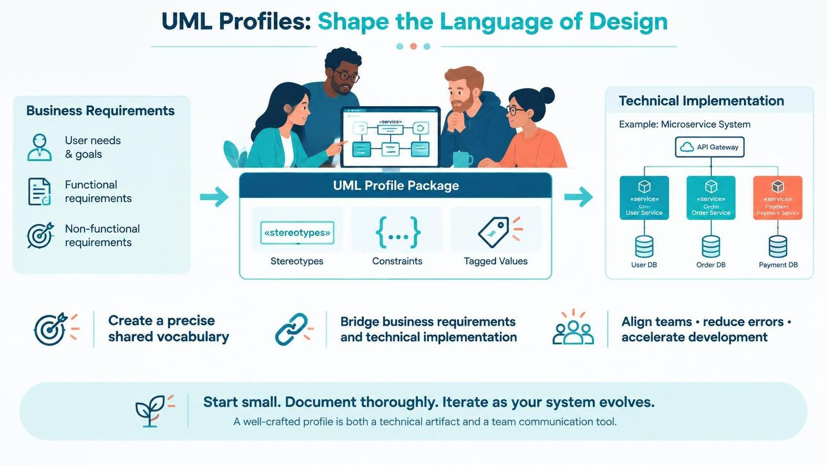

Introduction
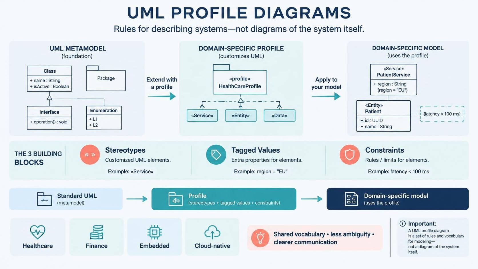
What is a Profile Diagram? 🧩
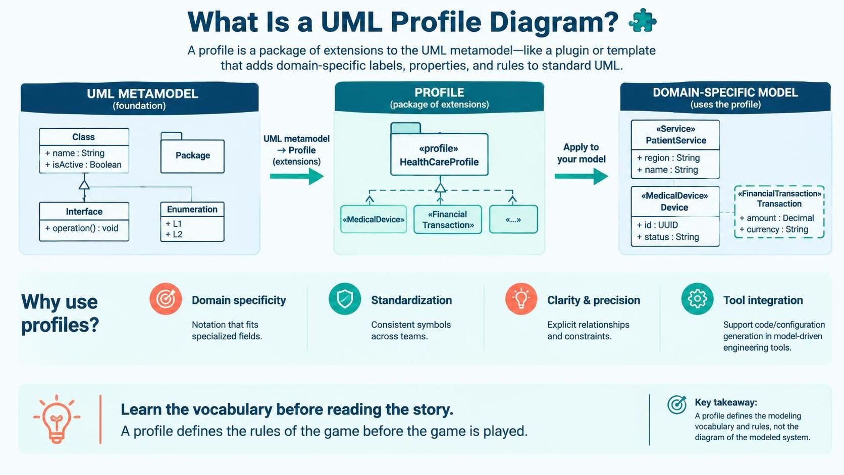
At its core, a Profile Diagram defines a profile—a package of extensions to the UML metamodel. Think of it as a plugin or a template that adds new icons, labels, and behaviors to standard UML elements.
Why Use Profile Diagrams?
- Domain Specificity: Create notations that resonate with stakeholders in specialized fields (e.g.,
<\<MedicalDevice>>or<\<FinancialTransaction>>). - Standardization: Ensure consistent usage of symbols across large teams and projects.
- Clarity & Precision: Reduce ambiguity by explicitly defining how elements relate and what constraints they must satisfy.
- Tool Integration: Enable model-driven engineering (MDE) tools to generate code or configurations based on custom stereotypes.
Key Insight: When you read a profile diagram, you are learning the vocabulary before reading the story. It defines the rules of the game before the game is played.
Core Components of a Profile Diagram 🏗️
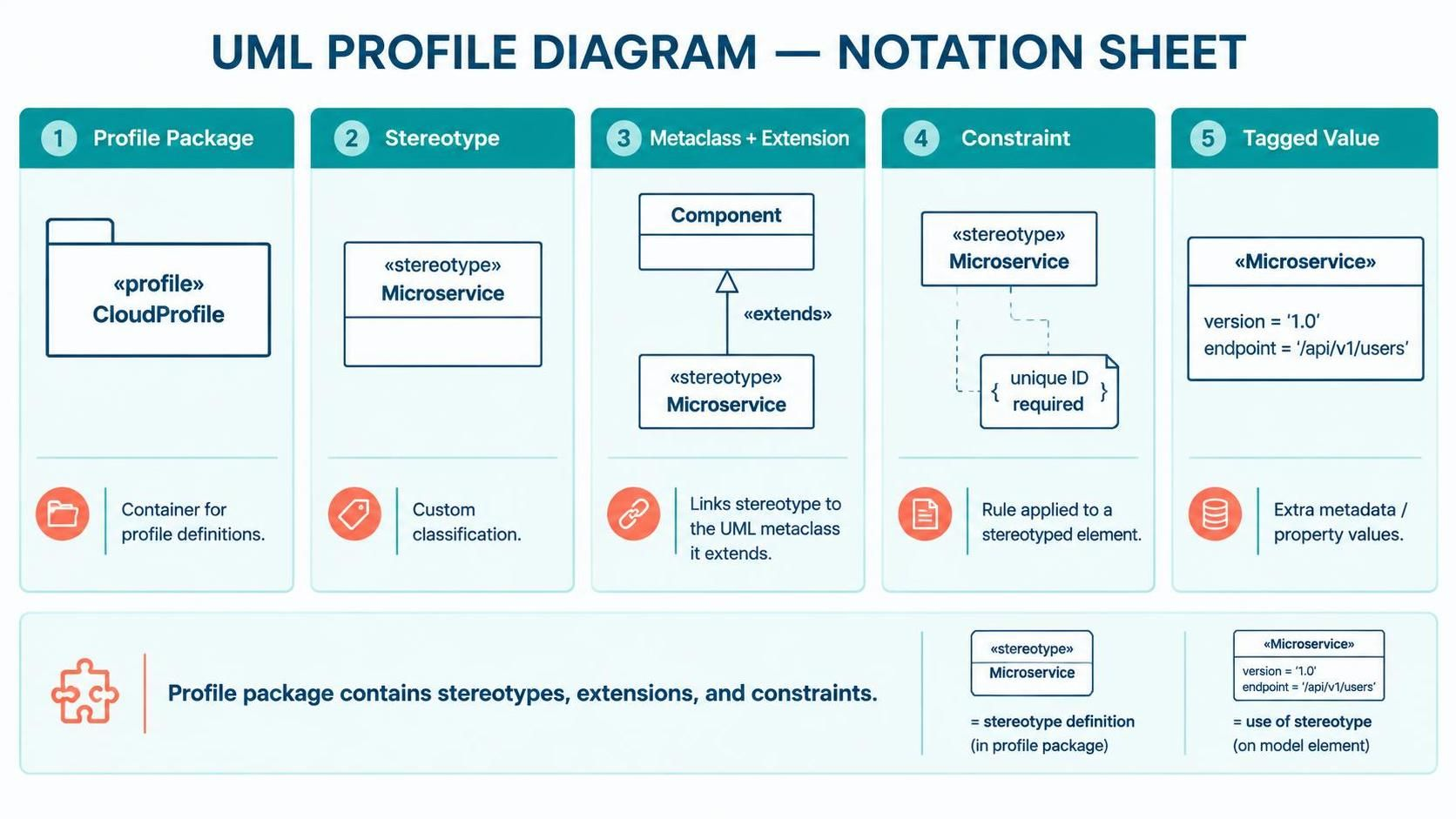
1. Profile Package
<<profile>> and holds stereotypes, extensions, and constraints.2. Stereotype
<<Entity>>, <<Service>>, or <<API>>.3. Metaclass
Class metaclass to create a <<DatabaseTable>> stereotype, or extend Component to create a <<Microservice>>.4. Constraint
{ }. Example: { must have unique ID }.5. Tagged Value
version = "1.0", priority = "High", or endpoint = "/api/v1/users".Key Concepts and Relationships 🔗
Stereotype Extension Mechanism
<<SecureService>>, I am actually using a Component, but with added security properties.”Relationship Types in Profile Diagrams
|
Relationship
|
Visual Style
|
Meaning
|
|---|---|---|
|
Extension
|
Dashed line with open arrow
|
Connects a stereotype to its base metaclass
|
|
Dependency
|
Dashed line with open arrow
|
One element relies on another
|
|
Generalization
|
Solid line with hollow triangle
|
Inheritance between stereotypes (e.g.,
<<AdminUser>> inherits from <<User>>) |
|
Association
|
Solid line
|
Structural link between elements
|
Inheritance and Reusability
- Base Stereotype:
<<Service>> - Derived Stereotype:
<<SecureService>>(inherits all properties of<<Service>>and adds security constraints)
Practical Example: Defining a Profile in PlantUML 🌱
While Visual Paradigm provides a graphical interface for creating profiles, PlantUML allows you to define them using code. This is excellent for version control, documentation-as-code, and quick prototyping. Below is an example of how to define the Web Service API Profile we discussed earlier, using PlantUML’s @startuml syntax.
PlantUML Code for Web Service Profile
Render the Profile Diagram using VPasCode
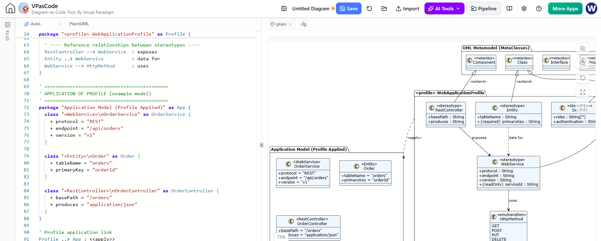
@startuml
' Define the Profile Package
package "WebServiceProfile" <<profile>> {

    ' Define the Stereotype <<API>> that extends the Component metaclass
    class "Component" as ComponentMetaclass

    stereotype "API" as APIStereotype {
        + endpoint: String
        + method: Enumeration {GET, POST, PUT, DELETE}
        + authRequired: Boolean
    }

    ' Define the Extension relationship (Stereotype extends Metaclass)
    APIStereotype -|> ComponentMetaclass : <<extend>>

    ' Add a Constraint to the Stereotype
    note right on link
        { endpoint must start with "/api" }
        { authRequired implies dependency on SecurityModule }
    end note

    ' Define another Stereotype <<SecureService>> that inherits from <<API>>
    stereotype "SecureService" as SecureServiceStereotype {
        + encryptionLevel: String
        + certificateExpiry: Date
    }

    ' Generalization: SecureService inherits from API
    SecureServiceStereotype -|> APIStereotype : <<generalize>>
}

' Example of Applying the Profile in a Component Diagram
package "SystemModel" {
    component "UserAPI" as UserAPIComp <<API>> {
        endpoint = "/api/v1/users"
        method = GET
        authRequired = true
    }

    component "PaymentAPI" as PaymentAPIComp <<SecureService>> {
        endpoint = "/api/v1/payments"
        method = POST
        authRequired = true
        encryptionLevel = "AES-256"
    }

    component "SecurityModule" as SecMod

    ' Dependency to satisfy constraint
    UserAPIComp ..> SecMod : uses
    PaymentAPIComp ..> SecMod : uses
}
@enduml
Full Diagram export from VPasCode:
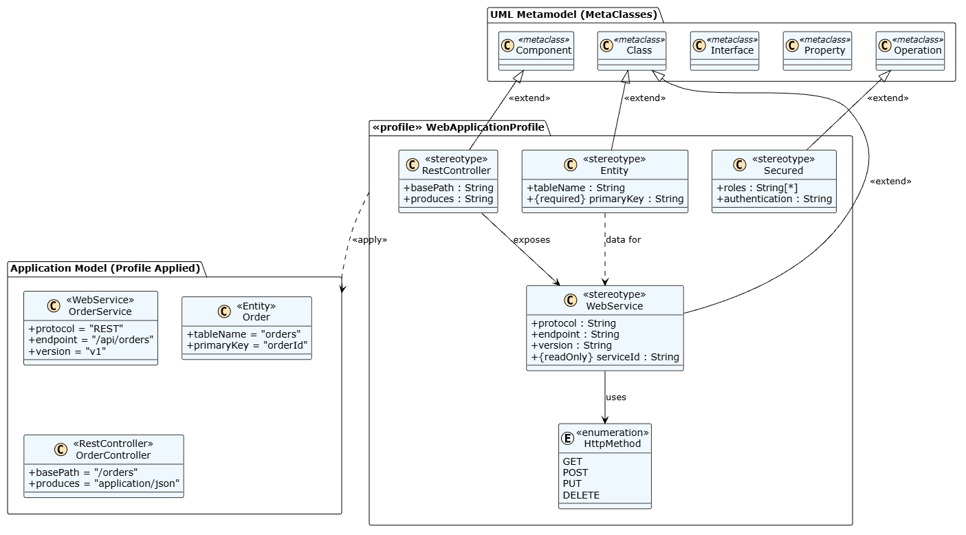
Breakdown of the Code
-
package "WebServiceProfile" <<profile>>: Defines the profile package container. -
stereotype "API": Creates a new stereotype namedAPI. -
+ endpoint: String: Defines tagged values (properties) for the stereotype. -
APIStereotype -|> ComponentMetaclass : <<extend>>: Shows that the<<API>>stereotype extends the baseComponentmetaclass. The-|>arrow indicates generalization/extension. -
note right on link: Adds constraints as notes attached to the extension relationship. -
SecureServiceStereotype -|> APIStereotype: Demonstrates inheritance between stereotypes. -
component "UserAPI" <<API>>: Shows how to apply the stereotype to an actual component in your model. The tagged values are listed inside the component block.
How to Use This in Practice
-
Copy-Paste into PlantUML Editor: Paste the code into any PlantUML live editor (like plantuml.com) to visualize the profile structure.
-
Integrate into Documentation: Include this code in your Markdown files or Confluence pages to keep your profile definitions version-controlled and easily updatable.
-
Generate Diagrams: Use PlantUML plugins in IDEs (VS Code, IntelliJ) or CI/CD pipelines to automatically generate updated profile diagrams whenever the code changes.
This approach ensures that your profile definitions are precise, reproducible, and integrated into your development workflow.
Tooling: Creating Profile Diagrams in Visual Paradigm
Visual Paradigm is a powerful UML modeling tool that supports profile creation and application. Here’s how to get started:
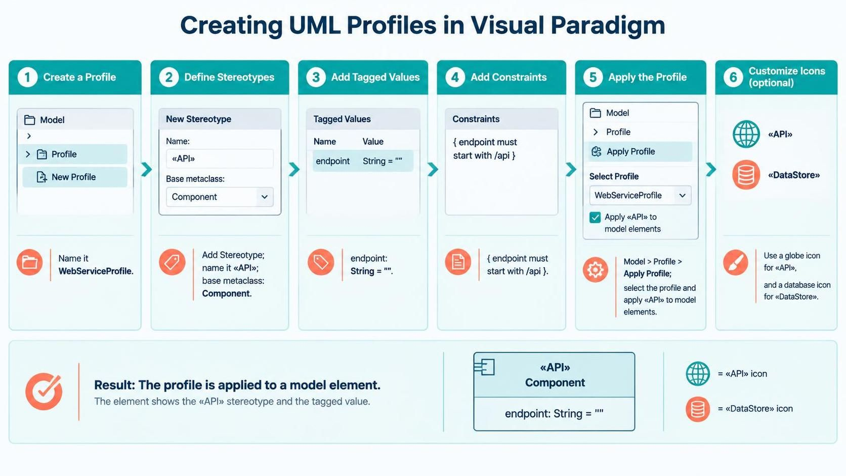
Step 1: Create a New Profile
- Open Visual Paradigm.
- Go to Model > Profile > New Profile.
- Name your profile (e.g., “WebServiceProfile”).
Step 2: Define Stereotypes
- Right-click the profile package and select Add Stereotype.
- Name the stereotype (e.g.,
API). - Select the base metaclass it extends (e.g.,
Component).
Step 3: Add Tagged Values
- Inside the stereotype definition, add Tagged Values.
- Define name, type, and default value (e.g.,
endpoint: String = "").
Step 4: Add Constraints
- Use the Constraint field to define rules.
- Write in natural language or OCL (e.g.,
{ endpoint must start with /api }).
Step 5: Apply the Profile to Your Model
- Go to Model > Profile > Apply Profile.
- Select your custom profile.
- Now, when you create elements in your diagrams, you can apply the custom stereotypes via the property panel.
Step 6: Customize Icons (Optional)
<<API>> and a database icon to <<DataStore>>.Step-by-Step Guide to Reading Profile Diagrams 🧭
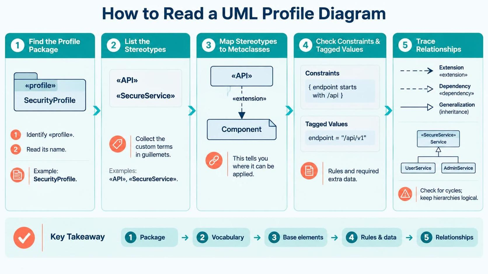
Step 1: Identify the Profile Package
<<profile>>. Note its name to understand the domain (e.g., “SecurityProfile,” “IoTProfile”).Step 2: List All Stereotypes
<< >>). These are the custom vocabulary terms. Highlight or list them.Step 3: Map Stereotypes to Metaclasses
<<API>> be applied to a Class? Only if it extends Class).Step 4: Review Constraints and Tagged Values
{ } and note the tagged values. These define the rules and extra data you must provide when using the stereotype.Step 5: Trace Relationships
Best Practices for Modeling with Profiles ✅
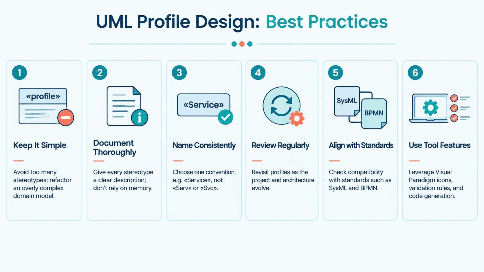
- Keep It Simple: Avoid creating too many stereotypes. If a concept is overly complex, consider refactoring the domain model instead.
- Document Thoroughly: Every stereotype should have a clear description. Do not rely on memory or implicit knowledge.
- Consistent Naming: Use consistent naming conventions (e.g., always use
<<Service>>, not<<Serv>>or<<Svc>>). - Review Regularly: Profiles evolve with the project. Revisit them periodically to ensure they still align with system architecture.
- Align with Standards: Ensure your extensions do not conflict with industry standards (e.g., SysML, BPMN) unless necessary.
- Leverage Tool Features: Use Visual Paradigm’s icon customization, validation rules, and code generation features to maximize the value of your profiles.
Integrating Profiles with Other Diagrams 🔄
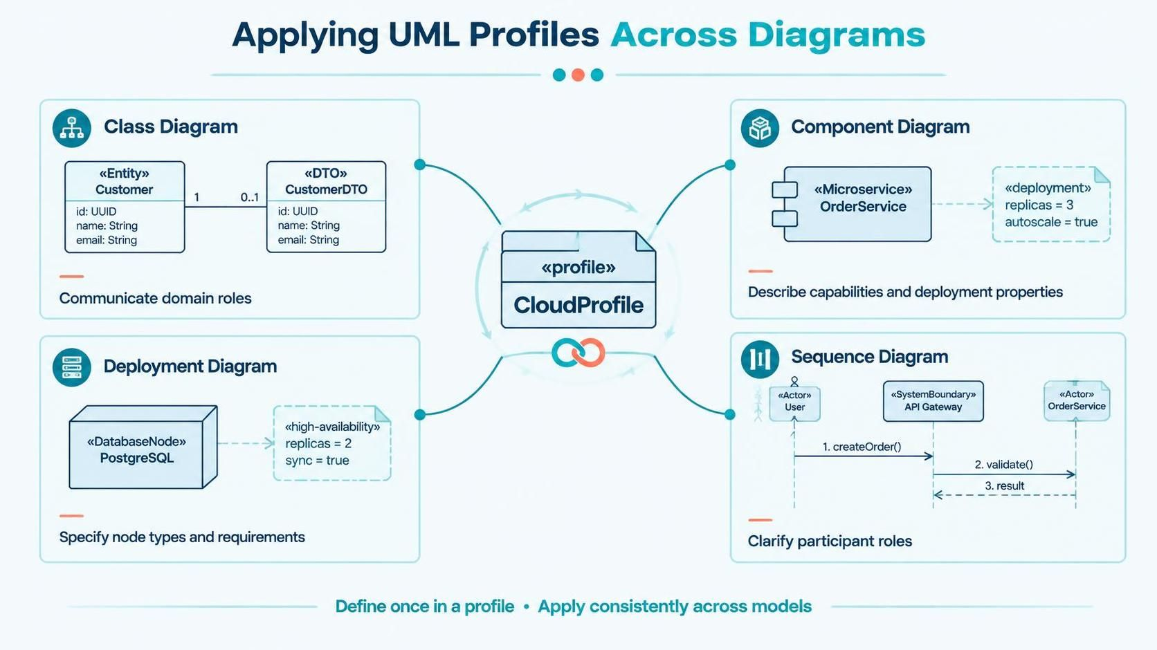
- Class Diagrams: Stereotypes appear on class boxes, instantly communicating domain roles (e.g.,
<<Entity>>,<<DTO>>). - Component Diagrams: Profiles define interfaces and capabilities. A
<<Microservice>>stereotype might imply specific deployment and scaling properties. - Deployment Diagrams: Profiles can specify node types. A
<<DatabaseNode>>stereotype might indicate high-availability storage requirements. - Sequence Diagrams: Stereotypes on lifelines can clarify the role of participants (e.g.,
<<Actor>>,<<SystemBoundary>>).
Troubleshooting Common Issues 🛠️
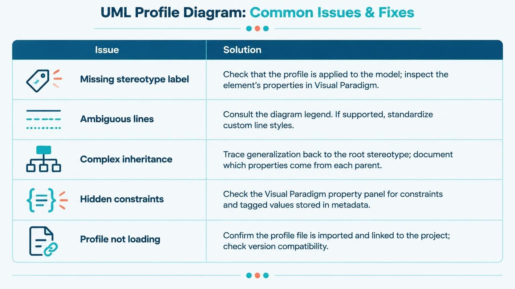
|
Issue
|
Solution
|
|---|---|
|
Missing Stereotype Label
|
Check if the profile is applied to the model. Verify the element’s properties in Visual Paradigm.
|
|
Ambiguous Lines
|
Refer to the diagram legend. Some tools allow custom line styles; ensure consistency.
|
|
Complex Inheritance
|
Trace generalization lines back to the root stereotype. Document which properties come from which parent.
|
|
Hidden Constraints
|
Some constraints are stored in metadata. Use Visual Paradigm’s property panel to view all constraints and tagged values.
|
|
Profile Not Loading
|
Ensure the profile file is correctly imported and linked to the project. Check for version compatibility.
|
Conclusion